I aim to totally breakdown the TSAL from the Formula student competition. This card for beginning team can be tricky to design.
Introduction
This article sums up everything I did personnaly on the TSAL, when I was working in a formula student team. This TSAL was suited for rule of the FSG 2023. I don’t guarentee that this TSAL model will be rule compliant and everything need to be well understood by your team in order to pass scrutineering.
This guide is more about what are the key component of the TSAL and how do they work.
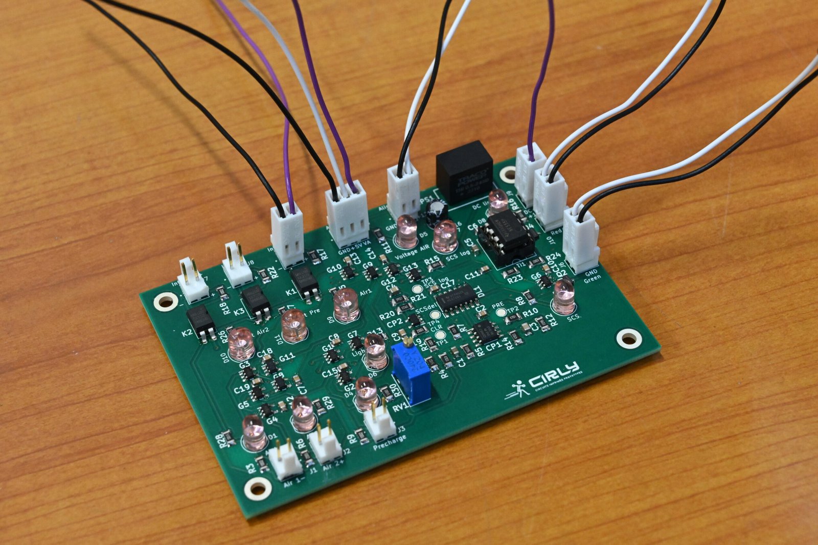
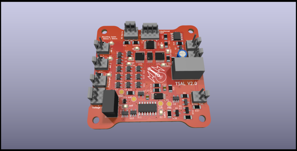
Card overview
We will know go in detail in each the component of the TSAL. The TSAL is composed of a green light and a red light. Each light is ruled by a set of condition and design principle on how do they need to light. Our card and the following article is written with positive logic convention : logic 0 is 0V.
Green light main rules
The green light need to be turned on when every power relay in the car is opened :
- Precharge
- AIR negative pole
- AIR positive pole
- less than 50V are detected on the AIR in the TSAC on the vehicle side.
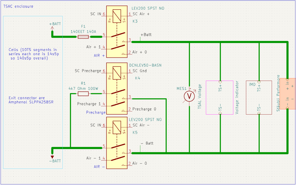
The schematic above represent the classical relays distribution inside the TSAC.
Red light main rules
The red light need to flash whenever the voltage on the pole of the DC-link capacitor are above 60V DC (other value for AC)
Green light latching
This set of rule are the trickier, I will largely justify this point.
TSAL guarentee the security of the vehicle. In this sense it needs to cover any failure, because one can be electrotuded if the TSAL mislead somebody into thinking that the vehicle is safe ! for this aim two seemingly complex rule are written, the EV4.10.13 and EV4.10.14. I will explain how to implement it and why are they here.
Without the Latching mechanism, as an exemple we will break each component at a time and see if we can notice a problem thanks to the TSAL.
- Red light voltage detect signal is always below 60V : TSAL is off when green goes off. We can detect failure.
- Red light voltage detect signal is always over 60V : TSAL is flashing orange and green at startup. We can detect failure.
- one AIR signal is always opened : We cannot proceed to detect this failure !
- one AIR signal is always closed : the TSAL green is off at start. We can detect failure.
- The green voltage detect signal is always below 60V : We cannot proceed to detect this failure !
- The green voltage detect signal is always over 60V : The TSAL green is off at start. We can detect failure.
Following the list up here, at startup we cannot detect already two cases of the 6 breakout. We want to be sure that the TSAL won’t show green if there is still voltage outside of the TSAC. This case can become dangerous if chained with other issue. So we need to detect this state. The only way to decide wether the AIR is opened or if the cable is not connected is to compare AIR state with wether or not we want it to be closed.
To do this we need to have the intentionnal state of the AIR coming to the TSAL. Since the intentionnal state are SCS compliant we can detect if they are shorted to ground, to supply or open circuit. Thanks to this we erase any issue with it concerning connectivity. (We need to have this feature on the VCU).
Relay intentionnal fault truth Table
The following Table translate the Latching rule into an actual truth table that enable us to detect wether or not a Relay output is faulty (following the intentionnal state). The relays are normally opened so sending 12V will closed them.
| Relay | Int | SCS Output | Int_Logic | Rel_Logic | Commentary |
| Closed | 12V | 0 | 1 | 0 | No issue |
| Opened | 12V | 1 | 1 | 1 | Faulty |
| Closed | 0V | 0 | 0 | 0 | the intentional state of the used (auxiliary) contact is opened |
| Opened | 0V | 0 | 0 | 1 | No issue |
Voltage detection intentionnal fault truth Table
The same goes for detecting if the voltage detection is faulty. if the intentionnal relay state leading to a voltage detection differs from the actual reading of our voltage detection it means there is a fault in our detection.
The intentionnal relay state leading to a voltage detection is set to logic 1 when :
- Intentionnal AIR 1 is closed (12V input)
- Intentionnal AIR 2 is closed (12V input)
The following Table translate the Latching rule into an actual truth table that enable us to detect wether or not our Voltage detection system is faulty. Our voltage detection mechanism send logic 1 when no voltage is detected (VoltageAir_logic).
| VoltageAIR | IntDetect | VoltageAir_Logic | SCS | Commentary |
| 50 V | 1 | 0 | 0 | No issue |
| 50 V | 0 | 0 | 0 | No intentionnal voltage |
| 0 V | 1 | 1 | 1 | Faulty |
| 0 V | 0 | 1 | 0 | No issue |
Card breakdown
Now we will go on every different system and explain their behavior.
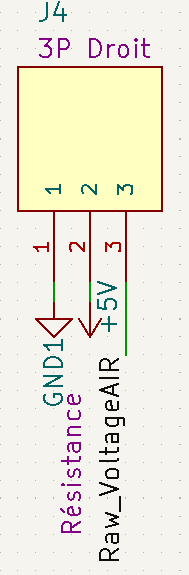
Non SCS signal input
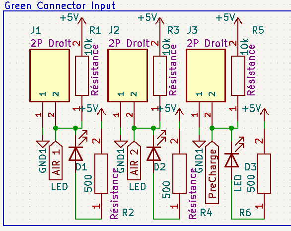
This system detects each state of secondary relays. We send 5V to one of the end of the relay through a resistance and if it is pulled down it means that the relays is closed. 5V means relay opened and 0V means relays closed. A LED is implemented in a way that when relay is closed the LED light up.
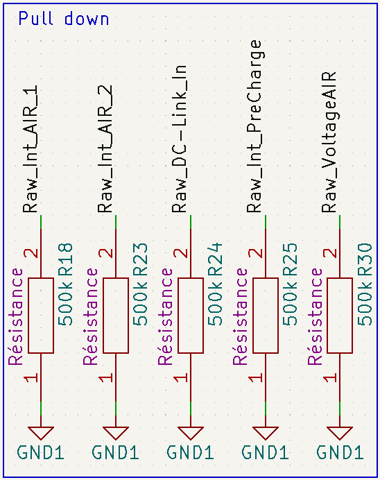
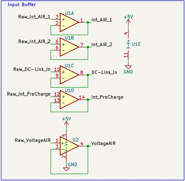
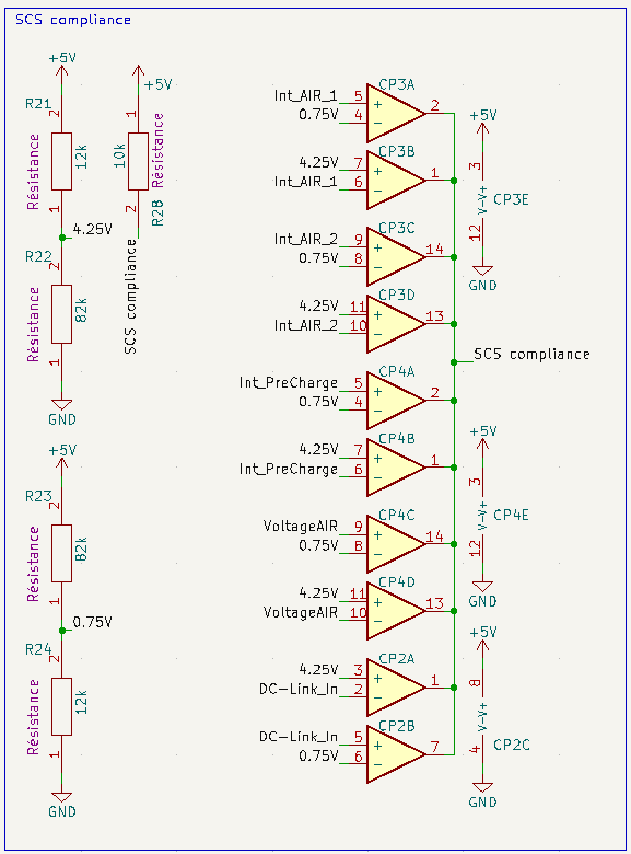
SCS signal input
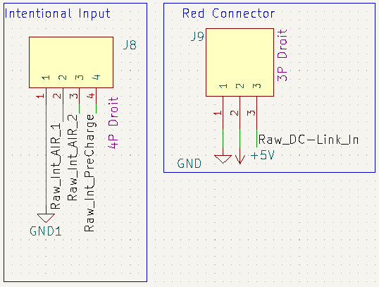
Rules states that all the other input of the card need to be SCS rule compliant. The explanation on this section will be pretty quick because this implementation of SCS signal has already been detailed in another article.
- Pull down to detect open circuit.
- Add buffer to signal to get back to low impedence signal.
- Detect if the signal lies between 0.75V and 4.25V.
Red light mechanism
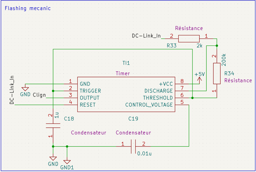
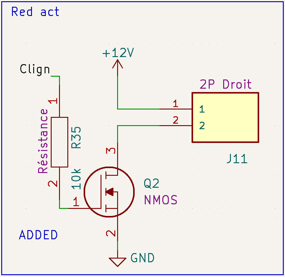
The Red light lightning mechanism need to be totally separated from the green light mechanism. This contraption is based on NE555 for timing. We trigger a NMOS to directly power drive the red light.
Green light mechanism
Rules states that green light should have a latching mechanism. This mechanism makes the green light more complex to design. In the next section, I will breakdown every part of the green light
Green light lightning condition
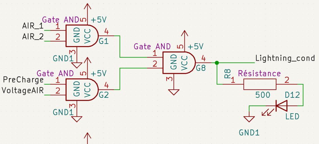
The green light Condition is just a AND between all 4 input. A LED is implemented in a way it lights up when the condition is valid
Green ligh fault condition
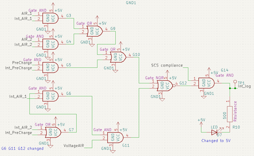
I will explain each part of this scheme :
- Upper Left section is the one that detect if Relays signal is different from intentionnal relays (cf. SCS Truth table Relays fault detection)
- Lower Left section detects if Air Voltage detection is at fault. (cf. SCS truth table Voltage fault detection)
- Mid Right section make a global NOR between the 4 differents system (3 relays and voltage detection). It needs to be a NOR because a logic 1 means no error (cf. Latching falling edge mechanism)
- When no SCS fault is detected SCS compliance is high so we ADD after the signal Inversion
A LED is implemented in a way that it lights up when error is detected. (NOR output to 0V or SCS compliance to 0)
Latching inition mechanism
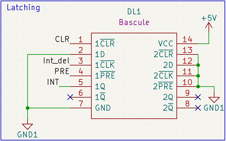
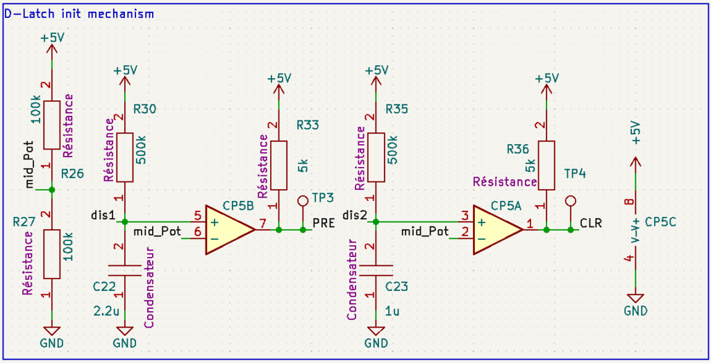
The Latching and D-latch init mechanism are designed in a way that the latching can be reset only thanks to a LV power cycle. the system is based on a standard automotive D-latch.
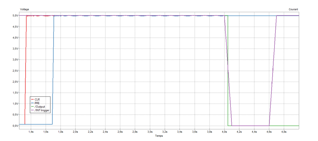
The following time table shows how PRE,CLR, INT(output) and Int del(INT trigger) works :
Intentionnal fault delay
The formula student rule state that we can have a delay between the fault detection and the detection (to counteract mis-reading of an error). We have also implemented a inition security that force the system to latch when the system is faulty at start. PRE is low during all the inition phase that force C21 to charge even if Int_Log is already in fault state (LOW) at start.
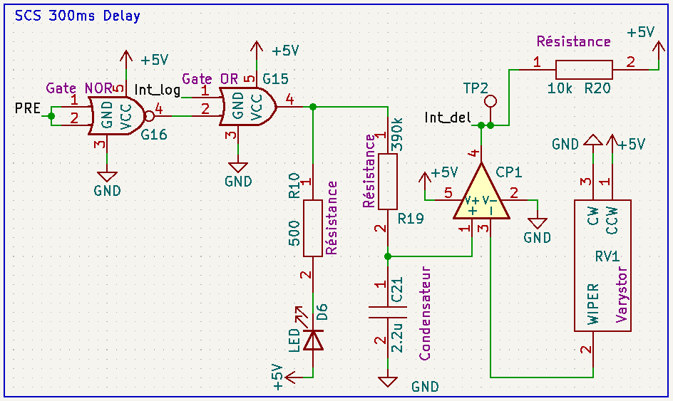
This system delay “Int log” from a value that we can choose with the Varystor. A led is implemented in a way that she lights up when INT is low. (system triggered)
Green light LED driver
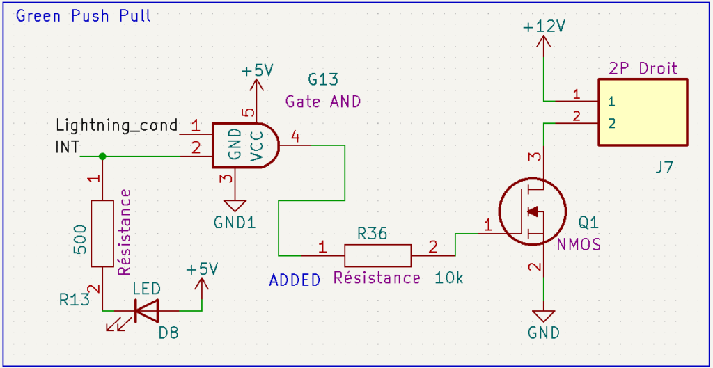
A comparison is done between the latching result and the lightning condition to drive a MOSFET.
LED indicator sum up
I will sum up each LED indicator with their respective lightning condition
- INT LED : Lights up when system is latched down due to error
- Light_cond LED : Lights up when relays are in a configuration that indicates safe operation (without latching TSAL is light up green)
- Int_log LED : Lights up when SCS or Relays configuration error is detected. (just before latching down)
- Relays LED : Lights up when relays is closed.
- Intentionnal relays LED : lights up when relays should be closed.
- VoltageAIR LED : lights up when voltage is under 60V.
- DC-Link LED : lights up when voltage is above 60V. (equivalent of TSAL red is flashing)
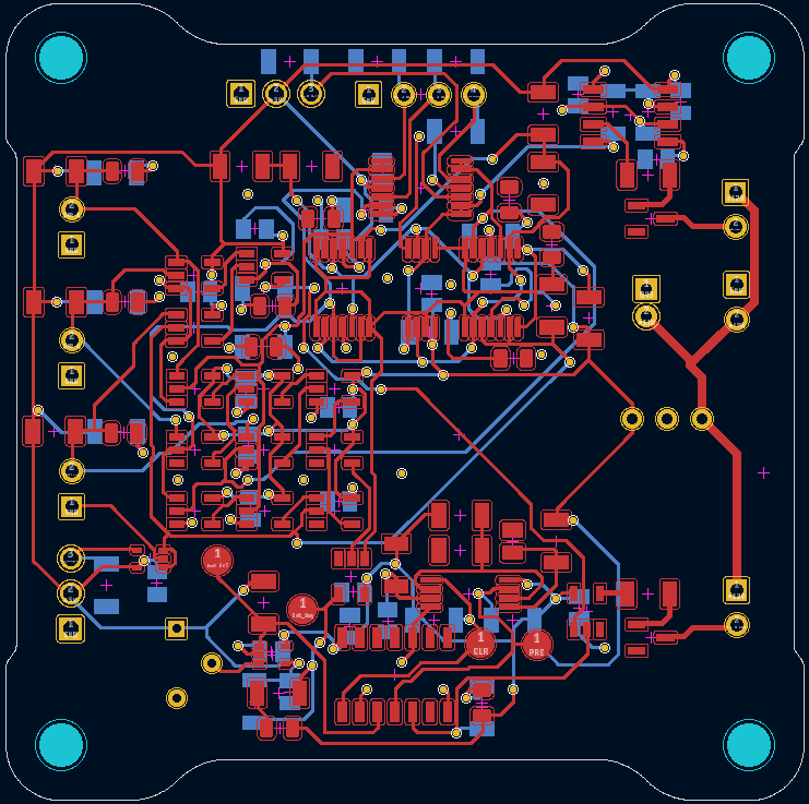
Card rooting breakdown
The rooting is pretty standard I will just show some screen shot before the download link. The card got components on both side (capacitor and resistance on other side only).
Download links
The bill of material doesn’t include resistor, capacitor and SMD led that are all standard component.
Disclaimer
Until I update this post to give feedback about the actual making of this board., this file is given “as is”, I may have done mistake in the making.
If you want to produce this exact card please keep my logo on it. It isn’t related to my former FS team, it just means that I made it ^^.
Leave a Reply