In this quick article, we’ll make some hardware modifications to an ST-Link V2 clone to enable software flashing using the reset pin.
Introduction
Why do we need to do this? In some projects, you’ll need to use the reset pin of the ST-Link V2. This pin is used to reset the chip just before flashing because the chip becomes available for flashing during this time. The issue is that, in ST-Link V2 clones, the reset pin is only configured for the reset behavior of STM8 chips. This means you won’t be able to use this pin when flashing STM32 chips.
Alternatives
If you’re reading this, you might already have an ST-Link V2 clone with this hardware issue. The market is flooded with clones, and genuine ST products can be hard to find or out of stock. However, there’s a solution: you could buy a Nucleo board, which is widely available.
The Nucleo boards are ST’s development board family (similar to Arduino), and each Nucleo comes with an ST-Link V2 PCB that can be detached from the board. Depending on your country, purchasing a Nucleo board for your project might be about the same price as buying an ST-Link V2, and you get a development board with it!
Explanation
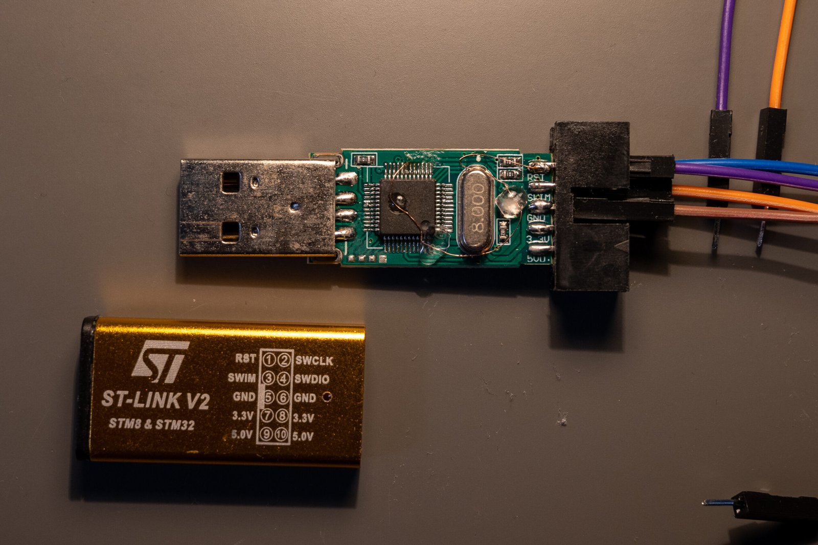
Let’s modify this chip !!
Material required
The hack is quite simple, but it still involves working with microelectronics, so you need to come prepared. In the future, I’ll write an article explaining my workspace, but for now, here’s a quick list of what you’ll need:
- Precision soldering iron (the TS-101 is great)
- Enameled copper wire
- Flux
- Fume extractor (important because flux fumes can be harmful)
What are we trying to achieve
You can skip this part if you’re not interested in explanation.
Let’s take a look at the schematics of the Nucleo board to understand how to wire the ST-Link reset pin.

As you can see in the Nucleo board ST-Link V2 schematic (above), the NRST pin is connected to pin PB0. Therefore, we will need to solder this pin to the NRST output from the chip.
Soldering
If I’m not too lazy, I might upload a video of the whole process. For now, I’ll just include pictures. The key is to use plenty of flux to make the process smoother.
Once the tiny cable is soldered, you can secure everything with UV resin or a solder mask.

Test
You can now test the chip by enabling ‘Hardware reset.’ You should see your microcontroller unit blinking due to the reset.
Leave a Reply