
How to detect open circuit or shorted to ground or to supply signal failure ? this article explains how to achieve SCS rule compliance in formula student.
This article is written in a way that people from Formula student team can understand a way to deal with System Critical Signal signal. However it can help anyone that want to detect open circuit or signal shorted to ground or supply voltage in any project.
Key principle and rule
The main goal is to detect a set of different things detailled in the System Critical Signal (SCS) section of the FSG rules :
- Failures of signals transmitted by cable:
- Open circuit
- Short circuit to ground
- Failures of analog sensor signals transmitted by cable:
- Short circuit to supply voltage
- Failures of sensor signals used in programmable devices:
- Implausibility due to out of range signals, e.g. mechanically impossible angle of
an angle sensor.
- Implausibility due to out of range signals, e.g. mechanically impossible angle of
- Failures of digitally transmitted signals by cable or wireless:
- Data corruption (e.g. checked by a checksum)
- Loss and delay of messages (e.g. checked by transmission time outs)
Today we will only focus on analog signal, defined by a. b. c. . Concerning the c., it needs to be implemented in a specific way but it isn’t really hard to do so (range detection thanks to comparator… ). Today we will focus on detecting Open circuit, Short circuit to ground and short circuit to supply voltage.
Realisation
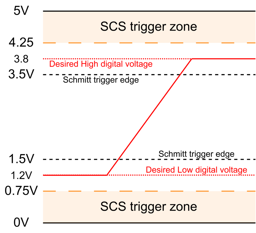
No more suspense ! To do so we will shift the working point of our sensor or signal from 0V to 5V to 1.2V to 3.8V. After we will only need to detect if our signal is between 0V and 0.75V and between 4.25V and 5V to detect a failure !
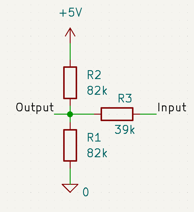
Thanks to a really simple circuit we can achieve this.
Design information
Since we want a symmetric design it is pretty easy to calculate resistance constraint :
\( R_1 = R_3 (\frac{V_s}{V_t}-2) \)
This formula is general and will help you design anything you want. Vs is supply voltage and Vt is the lowest voltage you want to target.

Now that we have the circuit that send our SCS compliant circuit, we need to design the other part of the circuit that will detect if everything is fine. The simplest is to use a bi-channel comparator. You need to choose a comparator that will be able to make comparison all the way from 0V to Vs (not Vs-2V like comparator with wide voltage input). It needs also to be open collector. (explaining in the detail)
Theorical detail
On this scheme we aim to close an optocoupler when we respect SCS (Sensor input between 0.75V and 4.25V). When using open-collector comparator we can chain their two output to make a boolean AND (active high logic).
| Comparator 1 | Comparator 2 | Voltage out | |
| Vin > 0.75V | Open “True / 5V” | Open “True / 5V” | 5V |
| Vin < 0.75V | Open “True / 5V” | Closed “False / 0V” | 0V |
| Vin > 4.25V | Closed “False / 0V” | Open “True / 5V” | 0V |
| Vin < 4.25V | Open “True / 5V” | Open “True / 5V” | 5V |

Thanks to R6 we are able to detect open-circuit.
After we only need to use our output to control an optocoupler, a relays or anything we want.
Leave a Reply