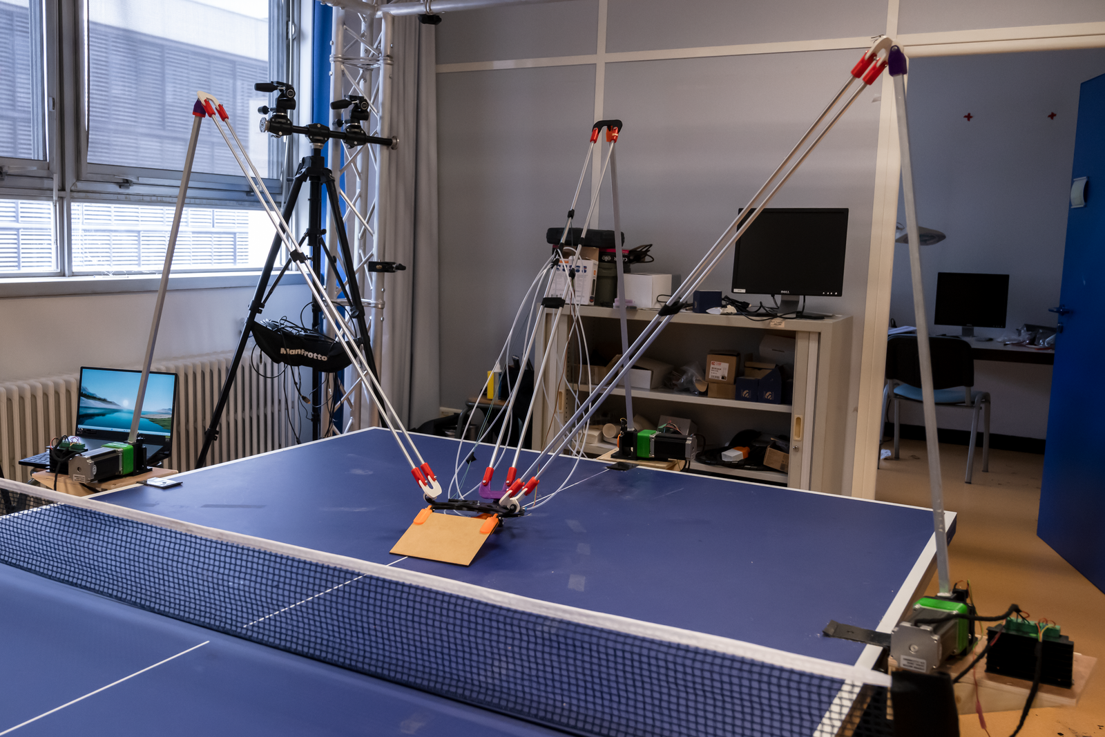
Today I want to talk about making proof of concept project, around the exemple of one of the robot I made : Table Tennis Trainer Robot.
This video only shows mechanical capabilities of the robot. These are pre-determined trajectories, started when the sound of ball emission is detected.
Introduction
First of all, I would like to thank the LIRIS laboratory at the Centrale Lyon engineering school for financing this project and making it possible. In particular, I would like to thank Romain Vuillemot for initiating this idea and seeking a proof of concept.
This article serves as a comprehensive guide to designing a robot, covering a range of key topics in robot creation. While ping pong enthusiasts may find it intriguing, its primary aim is to provide a step-by-step walkthrough for designing a robot.
Key aspects covered in this article include:
- Selecting the appropriate robot topology
- Understanding and utilizing inverse kinematics
- Choosing motors, reduction stages, and power dimensions
- Designing payload attachments, tailored to a specific example
- Crafting and sizing robot components
- Developing electrical harnesses and power distribution units
- Utilizing 3D printing for prototyping and assembly
- Implementing a feedforward control algorithm for the robot’s operation
Following these discussions, the article will conclude with an analysis of the robot’s actual performance and insights for future articles.
My philosophy on prototype design
This paragraph reflects my personal perspective on the importance of the proof of concept phase in project design.
Personally, the proof of concept phase of a project is my favorite part. There are no constraints on ideas, and one must be deeply curious about everything that could be related to the project.
During this phase, speed and flexibility are crucial. Each decision made significantly shapes the potential solutions. It’s essential to rely on rapid production methods, steering clear of complex machinery or advanced materials. The objective isn’t perfection; instead, it’s about demonstrating that the solution can function within constraints of time and resources. The aim is to showcase that with additional time and resources, the solution could realize its full potential.
Robot Topology
The initial step in addressing a challenge like “training a human at ping pong” is to determine the most suitable approach for building a robot to meet the requirements.
Initially, I brainstormed various approaches to tackle the problem and designed two potential robots, but ultimately constructed only one.
The key requirements for this robot include:
- High-speed displacement
- Precise orientation of the table tennis bat
- Capability to strike the ball
It’s evident that the payload of the robot needs to be minimal, equivalent to the weight of a table tennis bat or similar.
Based on these requirements, we can outline a range of potential robot topologies, including:
- Moving robot (such as a drone or a car roaming on the table)
- Fixed gimbal array robot (an array of stationary robots on the table)
- String robot
- Conventional robot arm
In my view, each of these topologies could be somewhat viable, and I may explore additional options in future projects. However, for this specific challenge, I opted to pursue a conventional robot arm approach.
Some numbers
While prioritizing speed, it’s beneficial to establish a set of numerical parameters to define our robot. At the very least, we should specify:
- Size of the robot’s workspace
- Velocity of the payload
- Permissible orientations of the payload
Playspace size
The robot must maneuver freely over the surface of the ping pong table and effectively hit the majority of easy ping pong balls. The table measures 152.5cm in width and 137cm in length. Our aim is to design the robot to navigate across this rectangular area, although this requirement is subject to some flexibility.
Velocity of the payload
During a typical table tennis match, players make approximately one hit per second. This implies that if the robot is positioned in the middle of its playspace, it has 500 milliseconds to reach the receiving position after the opponent hits the ball. By combining this timing requirement with the playspace dimensions, we deduce that the robot must move at a speed of 7 meters per second.
Orientation of the payload
Unlike other parameters, this one doesn’t require much explanation. We simply want the table tennis bat to be capable of moving horizontally from left to right within an angle range of approximately -45° to 45°, and vertically from top to bottom within an angle range of 45° to -20°.
Robot Arm topology
When selecting or designing a robot arm to address a specific challenge, there exists almost a unique robot arm topology for each problem. In our table tennis scenario, we require a robot arm that is both fast and precise but does not need to lift heavy weights. In the industrial realm, such robots are primarily utilized for pick and place applications, swiftly moving and sorting light components on assembly lines.
SCARA robot


My initial attempt involved creating a SCARA robot with the elevation of the table tennis bat integrated into the payload.
Unfortunately, despite efforts to minimize the weight of the pod, the robot proved too heavy. No motor was able to meet the requirements for handling this level of inertia.
Delta Robot


In the field of robotics, parallel architecture typically allows for swift movement of a lightweight payload. This capability arises from the arrangement where actuators in parallel robots are typically anchored to the base part of the robot (the component attached to the ground).
After my initial attempt failed due to high inertia, I opted for a parallel architecture. With motors now situated on the base part, the payload could remain remarkably lightweight.
Inverse Kinematics
In order to be able to design the whole robot, I needed to get the rough dimension of every characteristic component of my Delta architecture. These key component are :
- Lenght of every arm
- Angle between arm
- Position of the baseplate
The easiest way to determine these values is to compute the inverse Kinematic of the robot and to optimise these values to meet our working place contrains.
Robot arm kinematics
In robotics, the logic behind the kinematics of parallel robots differs significantly from that of serial robots. In this article, I will focus primarily on the inverse kinematics of parallel robots, but I will touch upon the key differences.
In robotics, you can compute both forward kinematics and inverse kinematics for a robot. Forward kinematics provide the position and orientation of the robot’s end effector based on the values of each joint (angle, elongation, etc.), while inverse kinematics determine the values of each joint needed to achieve a desired position and orientation of the end effector. Both kinematic analyses serve different purposes and are useful in various scenarios.
Typically, inverse kinematics are easier to compute for parallel robots and more challenging for serial robots, whereas forward kinematics are easier for serial robots and more complex for parallel robots.
Delta robot inverse kinematics


Now, I will delve into the process of computing Inverse Kinematics for a Delta robot.
The computation of inverse kinematics can be performed for each arm individually. An arm consists of a Biceps, which is connected to the output of the motor and can rotate around a single axis, and a ForeArm, which is connected to the Biceps through two ball joints between the position of the Pod and the Biceps. Our objective is to determine the value of \(ih\), which will enable us to calculate the angle of the motor needed to achieve the desired position.
First we determine the point \(Nac_{proj}\) which is the projected of \(Nac_{Pos}\) on the Arm plane :
\( d = Arm_{pos} – Nac_{pos} \cdot Arm_{normal} \)
\( Nac_{proj} = Nac_{pos} + d Arm_{normal} \)
We can determine \( r_c \) with Pythagore’s theorem :
\( r_c = \sqrt{F_l^2 – d^2} \)
And \(c_d\) easily :
\( c_d = || Nac_{proj} – Arm_{pos}|| \)
Now we need to find the intersection between the two following circle : (\( Nac_{proj}\), \( r_c\) ) and (\( Arm_{pos}\), \( B_l\) ). So let’s determine \( h \)
Detail of the intersection of two circle
Let’s write Pythagore’s theorem for the two triangle :
\( h^2c_d^2 + i_h^2 = B_l^2 \)
\( (1-h)^2c_d^2 + i_h^2 = r_c^2 \)
By substitution we get :
\( h^2 – (1-h)^2 = \frac{B_l^2 – r_c^2 }{c_d^2} \)
\( h = \frac{B_l^2 – r_c^2 }{2c_d^2} + \frac{1}{2} \)
From \( h \) we have and so we have the angle for the arm.
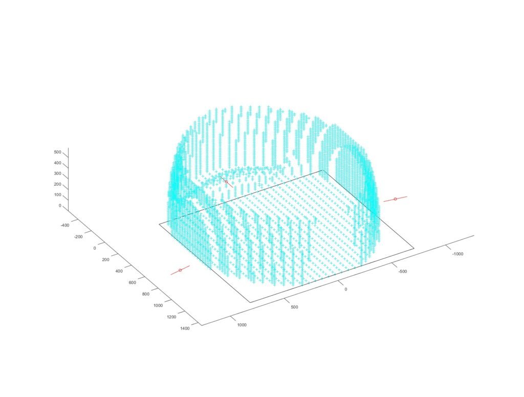
Working space computation and optimisation
The most straightforward approach to determine the working space of the robot is to evaluate the inverse kinematics on a 3D grid and verify the validity of the computations. Due to time constraints and numerous constraints, I performed the optimization manually. The result needed to maintain relatively short arm and forearm lengths for practical implementation.
Motor and reduction stage designing process
Selecting the right motor is paramount in robot design, as numerous projects fail due to an improper motor choice. Why is this? Fundamentally, choosing a motor is challenging, and selecting the appropriate reduction stage adds an additional layer of complexity.
In this section, I will elaborate extensively on my thought process for choosing the right motor. Initially, I will discuss motor types and reduction types in detail.
Motor types
There are various types of motors, each with distinct characteristics. Here’s a brief overview:
- Brushless motor : Mechanically simple, consisting of three coils. Requires a rotating magnetic field to drive rotation. Controlling brushless motors can be challenging, but they are cost-effective and durable.
- Brushed motor : also called DC current motor. Input Voltage determine the output torque. These motor relies on brushes to mechanically create a rotating magnetic field. There are less cheap and less durable but really easy to use.
- Step motor : You control this motor in angle, the motor is composed of a lot of tiny coil (some links in series) and you make the core turn by enerygising neighbour coil to make the core align with the energized coil.
- Servo motor : This not really a motor type but I put it in the list because a lot of people misunderstand what is this motor. Servo motor is composed of a brushed motor, a reduction stage, a potentiometer and a feedback controlller. The controller make the substraction between your input command and the actual angle of the output and ask the motor to turn in the right direction.
Reduction types
Reduction is crucial because it allows us to achieve the desired torque/speed ratio at the output. While we may aim for a specific output, it’s unlikely to find a motor that perfectly matches this requirement in terms of efficiency. Therefore, designing a reduction stage between the motor and the output enables us to convert the motor’s efficient torque/speed ratio into the desired torque/speed ratio at the output.
However, in hobbyist settings, producing steel gears like in industrial settings is not feasible. Instead, we must design reduction stages using 3D printed parts, which adds complexity to the process.

Some really famous reduction mechanism :


In 3D printing, creating everything from scratch presents challenges, especially when it comes to intricate parts like gears, which are complex to achieve with regular FDM 3D printing (although resin 3D printing may offer some advantages in this regard).
To address this limitation, I opt for designing Belt/Pulley systems with 3D printed pulleys and incorporate a cycloidal drive. This approach allows for the creation of efficient and functional reduction stages using 3D printed components, overcoming the limitations of traditional gear designs in FDM 3D printing.
Output characteristic
The first crucial step is to define the characteristics of your desired output:
- Output speed
- Output torque
- Reversability / feedback
Output Speed
Determining the output speed is prioritized over output torque because the torque requirement is contingent upon the desired speed. To establish the desired speed, we must refer back to our problem definition. In this case, we need to consider the required speed of the payload, which informs the speed of our output.
To derive the output speed, we revisit the requirement for the robot to move from the center of its play space to the edge within 500 milliseconds. Converting this positional requirement into an angular requirement, we need to travel approximately 30 degrees in around 500 milliseconds. This implies that the motor should operate at a speed of approximately 0.33 revolutions per second, or 20 revolutions per minute (rpm).
Output torque (this is wrong but I keep it here so my article is complete)
Despite its complexity, we must delve into dynamics and static equations to ascertain the torque required for our motor. When considering forces, we must compute both static and dynamic loads. This necessitates determining the weights of various components of our robot.
Previously, I underestimated the significance of the arm’s weight in the robot’s design, considering it negligible. However, upon reevaluation, while it may not be predominant, it cannot be disregarded entirely…
Let’s proceed with a lever arm calculation:
\( speed = \frac{RPM 2 pi}{60}\)
\( accel = \frac{speed}{ActionTime/2} \) In order to reach top speed in ActionTime we need to reach top acceleration in ActionTime/2
\( Torque = Arm_{length} accel Payload_{weight} \)
With some risk factor (1.5) we get a maximal torque of 3.3Nm.
Reversability and feedback
Since our primary objective is position control, unlike robots such as robot dogs or other mobile robots, we don’t require feedback on reaction forces. Therefore, our focus will remain on achieving precise positional control without the need for force feedback.
Power
In the end the power of our output need to be at least 7W
My choice for the robot
Choosing the right motor and reduction system is crucial to ensure it aligns perfectly with your desired output specifications and behavior:
- The robot doesn’t initially require a feedback loop for operation; it only needs to reach a desired output position.
- Precision is paramount, as even subtle changes in the motor angle can result in significant variations in the pod’s position.
- The motor should ideally rotate less than a full turn.
- High speed isn’t a priority.
Given these requirements, a stepper motor or a servo motor would be suitable choices. However, finding a servo motor capable of outputting the required torque proved unfeasible. Consequently, I opted for a stepper motor.
I selected the NEMA 23HS41-1804S motor, which offers 8W of power, 2.4Nm stall torque, and 1.50Nm at 60RPM. Initially, I believed this motor would provide sufficient torque, but it ultimately fell short of expectations.
Prioritizing torque over speed, I experimented with different reduction ratios. I initially designed belt pulley systems with ratios of 1:3.33 and later 1:5 (though the latter occasionally experienced belt tensioner failures). Ultimately, I settled on a cycloidal drive with a 1:10 ratio, which proved reliable despite the challenges encountered. I plan to detail the design process of the cycloidal drive in a future article, as it was both enjoyable and challenging.


Payload designing thought process
The primary innovation of my robot compared to conventional Delta robots is the attachment of a table tennis bat to the payload. The objective was to create an ultra-lightweight bat capable of rotating on both axes to return table tennis balls. Typically, such systems utilize motors, hydraulic, or pneumatic mechanisms. However, due to cost considerations, hydraulic and pneumatic systems were deemed impractical for my project.
When designing a cable-driven actuation system, several key factors must be considered:
- Cable stiffness: The stiffness of the cable directly impacts the precision of the commands. Stiffer cables result in more precise movements.
- Cable guide material: The material used for the cable guides must allow the cable to move freely to enable long-range actuation without resistance or friction.
- Cable tension mechanism: A mechanism must be designed to maintain constant tension in the cable at all times. This ensures consistent and reliable actuation of the system.

I designed two cable driven actuators for the robot :
- The first one is a rotating actuator that move all the payloas from left to right.
- The second one is a linear actuator that enable a sturdy rotation of the tennis bat.
This system enables sturdy enough movement that can handle the shot of a table tennis ball on it. I used Kevlar string that are highly stiff and enable really precise movement.
The string tensionner mecanism is made thanks to a twisted iron wire.


End Stop has been added in order to have reference position of the pod.
Electrical Harness
This phase is undoubtedly my favorite. It’s not particularly challenging, but it demands perfection. With the motor’s power consumption known, all aspects of power management fall into place.
Component selection
Now you choose every other electrical component in order to make it works. The component can be listed in the following categories :
- Sensors (end stop, angle, acceleration sensor…)
- Power unit (motor controller, power distribution unit…)
- computing unit (arduino, raspberry pi, microcontroller…)
- Human interface (Button, computer interfacing, light)
We can do the actual list :
- Each of the motors need an driver and an end-stop button for position reference.
- We will interface through an arduino MEGA.
- To get a real harness that could be transported, I choose to use DIN8 connector for control signal and Versa-Lock connector for power.
- We need a 5V supply for the arduino mega and a 38V supply for our motors.
- At the end we need a supply connector to plug our robot to electrical outlet.
Electrical harness design
Now that you have every component, it’s crucial to create a structured harness that guides you through the assembly process.

Part design
For this project, I was limited to 3D printing, wood laser cutting, and woodworking tools. Consequently, all design aspects had to adhere to these constraints. I iterated through multiple part designs until achieving sufficient strength, as there wasn’t ample time for part simulation; I relied solely on good practices. You can watch the assembly video here.
When designing parts, assembly considerations take precedence. With 3D printing and wood cutting, assembly relies primarily on screws and occasionally tight fits. Tight tolerances should be avoided, but when necessary, I employed hammer-fit bearings in my 3D parts.
A crucial aspect to consider is post-assembly adjustments. The simplest method for adjustability involves using loose connections secured by screws, such as when adjusting end stop values.
In the future, I will do a tutorial on how to do an assembly video from a .STEP assembly thanks to blender in no time ! (after I found the right method, I took 1h30 to animate this video)
Prototyping, component assembly
Usually if you were able to make an assembly video, it shouldn’t be really hard to assemble everything. I put in this section some pictures, I took during all the making process


Robot control
Now hopefully, it is one of the easiest part. The goal is to offer the capability for someone else to control freely your robot. Since we doesn’t have any feedback sensor, we can only control our robot with feedforward control (like CNC or 3D printer). The goal is to implement basic failsafe and the inverse kinematics computation directly on the controller. This will enable us to protect our robot from wrong command.
Robot Performance
In this section, I aim to showcase various results of the robot and demonstrate its actual performance in table tennis.
Initially, due to the absence of a feedback loop and some discrepancies in mechanical realization, the position of the robot head was inaccurate. However, it exhibited precision, indicating that a simple lookup table could rectify the observed position inaccuracies.
From a table tennis perspective, passive reflection of the ball was insufficient in most cases to return the ball effectively. This issue could be addressed by implementing fast movements of the robot’s pod, as demonstrated in the first video.
Despite the robot’s sufficient speed, employing a basic command law resulted in significant vibrations. Consequently, this led to extended settling times whenever the robot moved to a new position.
Conclusion
I hope you found this in-depth overview of my proof of concept project enjoyable and informative.
As evident from the dynamics section, I may have rushed through some computations, but mistakes are part of the learning process. Fortunately, my errors didn’t jeopardize the proof of concept, I only reduced the total speed of the robot. Perhaps in the future, I’ll revisit the dynamics computation when I have more time, although I haven’t yet found accessible resources for such calculations online.
To enhance the robot’s actual performance beyond what was described earlier, it would benefit from using less flexible parts (such as carbon rods instead of aluminum ones, and aluminum parts instead of 3D printed ones) and implementing a feedback loop on the motor or pod position to achieve better precision.
For practical use against a human opponent, a system would need to be developed to detect the ball and predict its trajectory.
Overall, this project was incredibly enjoyable, and I believe I learned a great deal during the process. I particularly enjoyed inventing the string rope mechanism. If I were to embark on another robot ping pong trainer project, I might explore a robot that moves around the table (such as a drone or car) and focus more on algorithm development rather than mechanical engineering, as the play space is too large for a robot arm alone.
Feel free to leave comments or ask questions. Additionally, if you come across any resources for easily computing the inverse dynamics of this type of robot, I would greatly appreciate it.
Leave a Reply