Today, I’m excited to introduce you to my simulation library on KiCad. Yes we can do simulation on this amazing software ! Let’s discover this together.
Introduction
KiCad is a popular choice among electronic hobbyists for a wide range of projects, from microcontroller boards to PCB antennas and even 8-bit computers. While it may not be widely known for simulation in forums, this open-source software is actually packed with impressive simulation features!
In this article, I’ll delve into how KiCad handles simulation and what it’s capable of achieving. I’ll also provide tips on finding simulation models online and share my personal KiCad library, complete with example projects for each component included.
For this article I use Kicad Version 8.0.0, release build.
Kicad Version 8.0.0
How timely for this article! KiCad Version 8.0.0 has just been released, with simulation being one of its key focuses!
Kicad, a simulation tool ?
KiCad comes equipped with a variety of simulators, including LTSpice, PSpice, and HSpice. What does this mean? Essentially, KiCad has the capability to run nearly every standard simulation model provided by manufacturers. In my experience, the majority of these models are PSpice models.
Let’s dive into Kicad Simulation aspect
The magic happens in the Schematic editor. Here, we can define various types of components :
- Simulated electrical component (your favorite OpAmp, resistor, capacitor, inductance…)
- Non-Simulated electrical component (decoupling capacitor, connector…)
- Simulation component (simulation ground, voltage source…)
To select the behavior of each component in your schematic, you can access the Attributes section in the Symbol property panel by pressing the key ‘E’ while selecting a component:
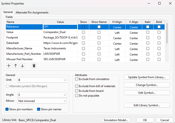
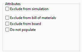
- Simulated electrical component : nothing ticked
- Non-simulated electrical component : Exclude from simulation ticked
- Simulation component : Exclude from BoM and board ticked
A component exemple : the potentiometer
Consider this scenario: You’re looking to integrate a varistor or potentiometer into your circuit to establish a precise voltage threshold. While these components are straightforward, they do come with certain parameters. Exploring their functionality within KiCad’s simulation environment presents an excellent opportunity to understand how KiCad handles circuit analysis and validation.
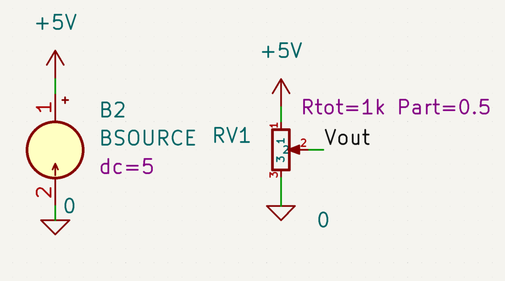
On our schematic we have a voltage source (Simulation component) and our Trimmer resistor. Let’s dive into the Trimmer resistor simulation parameter (access from component property)
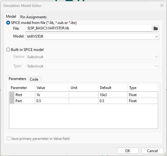
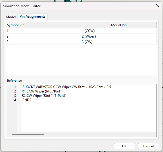
In the Model section, KiCad utilizes the component model VARYSTOR from a SPICE file named VARYSTOR.lib. This model incorporates two parameters, Rtot=1k and Part=0.5. Upon examining the pin assignment, it’s evident that each pin is appropriately assigned to its corresponding symbol pin. For a trimmer resistor, the Wiper pin represents the variable output of our potentiometer, ensuring our symbol is correctly configured.
In-schematic parameter setup
Notice that our model features two parameters named Rtot and Part. Typically, KiCad stores these parameters within the Simulation Model Editor. However, we have the option to link these parameters, allowing us to modify them directly in the schematic editor, as depicted in the first picture.
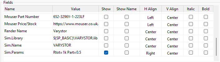
You need to add a Fields called Sim.Params with the different parameter separated by space formated like this : name=value
A little bit of Spice coding
This model has been handcrafted by myself, so I can provide insights into how it operates! Spice code differs significantly from other types of code; each line defines a component with its type, name, connections, and behavior.
The most effective approach is to study manufacturer libraries and Spice manuals to grasp the full range of possibilities offered by Spice. Unfortunately, there appears to be a limited amount of resources available on the internet for learning Spice programming…
Let’s dive into Varystor.lib :
.SUBCKT VARYSTOR CCW Wiper CW Rtot = 10e3 Part = 0.5
*I define a sub component called VARYSTOR with CCW Wiper CW as connection and base parameter value Rtot = 10e3 and Part=0.5
R1 CCW Wiper {Rtot*Part}
* I put a Resistance called R1 between CCW and Wiper of Value Rtot*Part
R2 CW Wiper {Rtot * (1-Part)}
* I put a Resistance called R2 between CW and Wiper of Value Rtot*(1-Part)
.ENDS
* end of the sub component definition
In KiCad, I’ve chosen the subcomponent VARYSTOR to represent the actual model of my component.
When downloading a Spice model from a manufacturer, you often need to create a subcircuit (subckt) with the correct pin order and the appropriate number of channels. For example, if you’re looking for a model of a quad OpAmp, you might only find a 1-channel model in the PSpice library. In this case, you would need to create a 4-channel subcomponent to accurately represent it:
.SUBCKT TLV9062_Mono IN+ VEE IN- OUT Vcc
*I define a sub component called TLV9062_Mono with IN+ VEE IN- OUT Vcc as connection
XU1A IN+ IN- Vcc VEE OUT TLV9062
*I put a component called XU1A that have connection IN+ IN- Vcc VEE OUT and follows the behavior of the (sub)component TLV9062
.ENDS
.SUBCKT TLV9062_Dual OUT1 IN1- IN1+ VEE IN2+ IN2- OUT2 Vcc
*I define a sub component called TLV9062_Dual with OUT1 IN1- IN1+ VEE IN2+ IN2- OUT2 Vcc as connection
XU1A IN1+ IN1- Vcc VEE OUT1 TLV9062
*I put a component called XU1A that have connection IN1+ IN1- Vcc VEE OUT1 and follows the behavior of the (sub)component TLV9062
XU1B IN2+ IN2- Vcc VEE OUT2 TLV9062
*I put a component called XU1B that have connection IN2+ IN2- Vcc VEE OUT2 and follows the behavior of the (sub)component TLV9062
.ENDS
.SUBCKT TLV9062_Quad OUT1 IN1- IN1+ VEE IN2+ IN2- OUT2 OUT3 IN3- IN3+ Vcc IN4+ IN4- OUT4
XU1A IN1+ IN1- Vcc VEE OUT1 TLV9062
XU1B IN2+ IN2- Vcc VEE OUT2 TLV9062
XU1C IN3+ IN3- Vcc VEE OUT3 TLV9062
XU1D IN4+ IN4- Vcc VEE OUT4 TLV9062
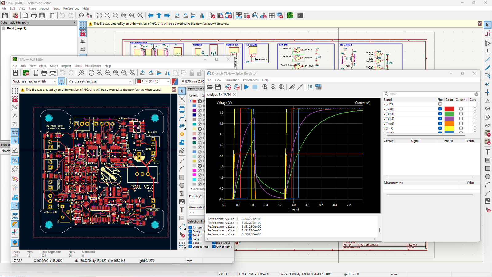
.ENDSSimulation panel
Now that you’ve completed your circuit, it’s time to run our simulation. To do this, we need to open the simulator panel, located in the Inspect tab.
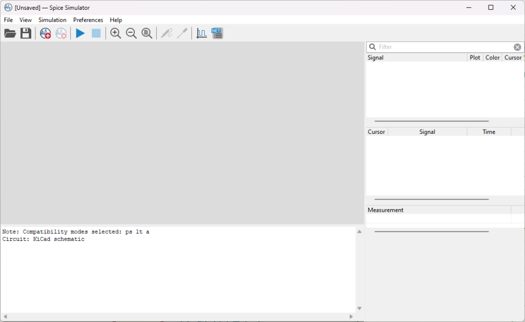
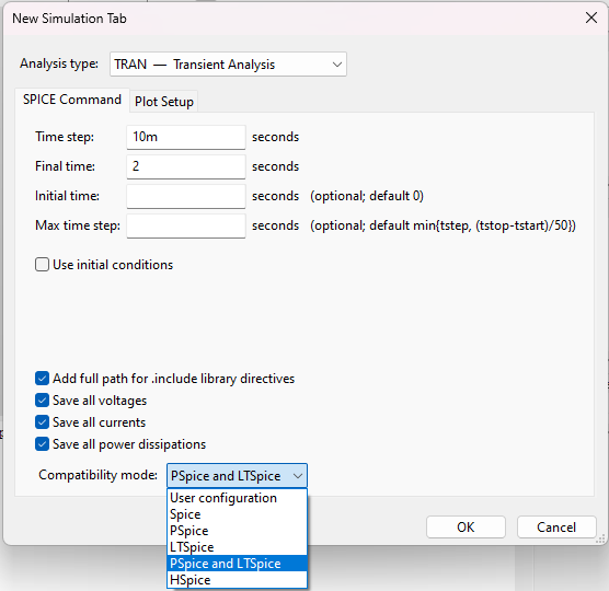
Before initiating a simulation, it’s essential to configure your simulation environment in the Simulation Command menu. Here, you can choose from various simulation presets. For FSAE boards, I primarily conduct transient simulations, which track the circuit’s behavior over time. Remember to select the appropriate compatibility mode; PSpice and LTSpice modes typically suffice for most simulations.
Once configured, simply click ‘Run’ to begin the simulation. You can then monitor different signals by using the Probe tool to click on the wires in the schematic.
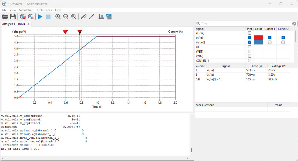
If you wish to conduct further analysis, you have the option to save all data in a CSV file for thorough examination. Alternatively, within KiCad, you can utilize cursors to inspect signals directly. Simply tick on the signal where you wish to place a cursor.
Build you own library
In this brief section, I’ll share some of my advice on building a library or selecting components for your project.
General advices
Later, I’ll delve deeper into this topic with a dedicated article, but for now, I’ll share a few helpful tips:
- For hobbyist don’t go lower than 0603 resistor/capacitor, it will be painful otherwise.
- Buy a set of resistor and capacitor it is way more easier.
- Use SMD led it is brighter, cheaper and more usefull.
- focus on few common different component packages : (the list above got size that you can solder pretty easily)
- SOIC
- SOT-23
- SC70
- TSSOP
- Only buy component that are in stock and not rated as End of production.
- 2.54mm pitch connector are really common. THT connector will resist more heavily.
- Use high-end voltage regulator, it will forgive your mistake and doesn’t fry when short circuit.
- Follow Typical application section in datasheet to avoid mistakes.
Find symbols and Spice model
Typically, you’ll find the symbol of a component for KiCad by using specialized search engines. Personally, I rely on Component Search Engine and SnapMagic. If your component isn’t available in these resources, it’s likely because you’re seeking something uncommon, and you may need to explore alternative options.
Finding Spice models can be more challenging. Generally, Mosfets, OpAmps, and other components are available on the manufacturer’s website, albeit sometimes in less accessible areas. For instance, Texas Instruments offers a wide range of models. In some cases, I search for general models like D-Latch and NE555. For transient simulations, you don’t always require highly precise models since you’re primarily interested in confirming behavior.
Formating your library
Now that you’ve selected your component and imported the symbol into your local or global library, it’s important to ensure uniformity across all components. If every component in your project shares the same component field, you can easily export your bill of materials with a single click, automating tasks such as generating Mouser carts or preparing files for board manufacturing companies. Personally, I check the following for each component:
- Field placement / visibility
- set the Datasheet field
- set the Manufacturer_Part_Number field
- set the Mouser Part Number field
- part has a standard footprint
- If the PSpice simulation field has the correct input/output and the correct file is linked
Overall you can check my library, you will see how everything is made.
My library
I’m thrilled to introduce you to my Simulation library for KiCad. This library is packed with simulations for standard and highly useful components!
Component list
Here is the list of the component :
- Comparator (Mono, Dual, Quad)
- OpAmp (Mono, Dual, Quad)
- D-Latch
- general use Diode, Resistor, capacitor
- AND, NAND, NOR, OR, XOR 1 channel gate
- PMOS, NMOS, Depletion NMOS
- Solid state relays
- NE555 Timer
- Trimmer Resistor
Exemple simulation file
I have made some exemple file for the different component and use case.
- Buffer OpAmp
- Comparator
- D-latch initialisation (TSAL Dlatch circuit)
- Pspice Initial Condition
- SCS Dual Comparator (SCS simulation circuit)
- Trimmer resistor
How to install the library
It’s straightforward to get started. Simply download the archive and import the symbol library and the footprint library. The symbol library, named Basic_SPICE.kicad_sym, can be found in the folder KicadLib\Basic_SPICE. The footprint library is located in the folder called Basic.pretty.
To ensure the simulation works smoothly and the 3D files display correctly, you’ll need to create two custom path in the preferences tab.
- The first one called BASIC_3D pointing to KicadLib\Basic_3D folder.
- The second one called SP_BASIC pointing to KicadLib\Basic_SPICE\Lib folder.
Annexes
I’m currently in the process of building another library for non-simulated components called Basic_UTIL. Additionally, I’ve included helpful internet resources in the help folder. Eventually, everything will be stored on GitHub for easy access.
Download link
You can download the latest version of my library from the link provided here.
Leave a Reply