Today, we will design and build the first version of a handheld CO2 monitor. This is a great way to learn a lot about electronics and experiment with different sensors.
Disclaimer
This version 1 CO2 monitor is not suitable for production or practical use. Consider this article as a story of my journey in electronics! If you’re interested in a functional product, stay tuned for the article on version 2, which will likely be published around October 2024. The mistakes are highlighted in red.
Motivation
Even though I don’t intend to sell this product, it’s always useful to check if a project addresses a need and whether similar products exist in the market. If a similar product already exists, you might be wasting your time reinventing something that’s already available. On the other hand, if there’s no demand for it, you could create something amazing, but no one will be interested (it’s unlikely that you’ll invent something people didn’t know they wanted!). I believe that if you pitch your idea and no one shows interest, either you need to present it differently, or your idea doesn’t solve a real problem.
In France, we have a yearly competition for unusual inventions. Many of these are creative ideas that solve very niche issues, which is great. However, I prefer to focus on problems or needs that attract a bit more attention.
Project requirement
What were my motivation to embark in this odd project ? At first it seems that a lot of CO2 monitor already exist in the market ! By stating my reason for this project we will be able to give a list for the requirement of the project !What motivated me to embark on this unusual project? At first glance, it seems like there are already plenty of CO2 monitors on the market! However, by outlining my reasons for taking on this project, we can establish a list of requirements for it.
Here are my requirements:
- Use a high-end sensor
- Operate on battery power
- Be small enough to fit on a keyring
- Require no charging or maintenance for a long period (at least ~3 months)
- Have an update period between 1 and 20 minutes
This is my wishlist! Now, let’s compare it with existing products on the market to see if this could be a unique offering. After doing some research online, I found:
- Price: between 30 and 60 euros
- Some are battery-operated, while others need to be plugged into the wall
- Sizes range from that of a glasses case to a weather station
- Battery-operated sensors have an autonomy of about 1 day
- Update periods range from 30 seconds to one minute
So, it looks like my idea isn’t currently available on the market and could fill a niche in the CO2 monitor category.
Market survey
Now we can ask people about our idea to see if they would be interested in buying it! Let’s conduct a quick qualitative and quantitative survey to gather some insights.
Qualitative survey
The best way to conduct a qualitative survey is to ask friends from different fields for their feedback on your idea. So, what was their feedback?
- The price range is good.
- The fact that you don’t need to worry about the battery is a strong point.
- The small size of the object is appealing.
- The purpose of the device seems a bit unclear; some viewed it as a gadget or niche product.
Quantitative survey
At my engineering school, we have a survey group, which is the best place to gather data! While this survey may be biased since it only targets engineering students, it’s better than having no data at all. Here are the results from 45 responses:
- Domain knowledge questions:


- Object characteristic:


- Attention:


When focusing on engineering students, there is considerable interest in this project, and their expectations aren’t too high. Based on this data, we should aim to price the product around 20 euros and make it roughly the size of a car key.
Market survey conclusion
Based on the results from both the quantitative and qualitative surveys, it’s clear that this project won’t be a breakthrough. Is that a bad thing? Not at all! I never intended for this product to revolutionize the world. I simply wanted to create something that doesn’t already exist and is somewhat useful. I’m actually quite happy with the survey results!
Introduction
Time to dive into the project! We know what we want to achieve: a lightweight CO2 monitor for around 30 euros. We will use the SCD40/41 CO2 sensor.
CO2 Sensor breakdown
This sensor uses spectroscopy photoacoustic technology to detect CO2. It emits infrared light that is finely tuned to the absorption band of CO2. When the CO2 molecules absorb this energy, it is converted into molecular vibrations. These vibrations cause variations in the pressure within the sensor chamber, which can be detected by a microphone. The change in pressure is proportional to the number of CO2 molecules present.

Hardware
The hardware component of a project like this is crucial, as it significantly impacts energy consumption. I decided to use PMOS transistors for the SD card, E-paper display, and CO2 sensor.
Part breakdown
We will go through each component one by one and select the appropriate microcontroller (MCU) for our project.
E-paper screen driver
I followed the typical application outlined in the E-paper screen’s datasheet. All connections are routed to a 24-position FPC connector.

The screen uses six cables for operation:
- Screen_BUSY: Goes low when the screen is busy updating.
- Screen_RES: Reset pin of the screen (requires setting the correct logic level).
- Screen_CS: Chip select for the SPI.
- D/C: Determines whether the SPI is sending data or a command.
- SCK: SPI clock.
- SDI: SPI data input.
CO2 probe
The CO2 probe is very simple to wire.
Even if it is easy, I managed to forgot to put pull-up resistor on I2C bus

I2C consists of two lines: SCL (clock) and SDA (data).
SD card
It’s quite simple to use the SD card with SPI. The connections include SD_CS for chip select, SCK for the clock, SDI for data input, and SDO for data output.

Microcontroller unit
Now that we have all the other components, we can choose an MCU that meets all our requirements. The best way to do this is to list everything we need and then pick the right MCU.
Requirements:
- SPI bus
- I2C bus
- 8 GPIO pins:
- SD_CS
- SD_PWR
- CO2_PWR
- Screen_PWR
- Screen_BUSY
- Screen_RES
- D/C
- Screen_CS
We’ll also focus on selecting a low-power MCU from a reputable brand. One great way to do this is to provide your requirements to ChatGPT and listen to its recommendations!
Initially, I created a PCB with a PIC MCU, but the PICkit required to program it costs 100€, and I couldn’t get the student discount because no one responded to my email. So, I switched to the STM32, opting for their L0 series for low power consumption.

Power supply
I choose to supply the chip with only one CR1225 battery of roughly 50mAh.
This was a bad idea, the whole consumme too much to run on 50mAh, it worked with two LR44 but overall it needs to be a rechargeable chip and it is the main argument for a V2
PCB rooting and panelisation
Now, we can jump into our schematic editor.
PCB rooting

Panelisation
When buying PCBs online, the price is usually the same for any board that is smaller than 100mm x 100mm. Since our board is quite small, we can fit multiple PCBs within a 100mm x 100mm area. There is a KiCad plugin called ‘panelization’ that helps with this process. In this article, I’ll just show you the result, but I will create a tutorial on panelization later.

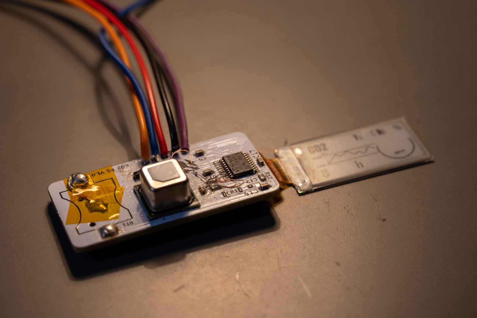
Actual realisation and Hardware patch

I needed to patch my I2C with tiny wire in order to have the pull-up resistor

Software
LET’S GO PROGRAMMING IN C. In order to enable the full capabilites of the STM32 we’re going to use the STM32CubeIDE in order to program our chip (no Arduino IDE but actually don’t be affraid it is nearly the same). In C no class, so everything is in our project, I took inspiration from arduino library and the recommanded code of the datasheet for the paper display, and made my own C header and code.
Quick C helper
You’re here so I assume you already know base of C through arduino. The main thing that change in STM32CubeIDE it is we get a real IDE with file management. As I said earlier there is no class in C, we can only import header file that are linked with C code file. It is pretty restrictive but that’s why it runs really fast.
Code structure
Image creation
I will just detail the way I create my background image for the E-paper display.
I found on the internet some paid software to create image for E-paper display (way to arange pixel in a good way) and complex free alternative (installing C library). I have made a one line script using ImageMagick in order to create the right header (instructions could be founded in the repository). As noted that the first bytes need to be discarded because they contain an header.
Bus communication
I needed to set up two communication buses: SPI for the screen and I2C for the CO2 probe. I used the pre-implemented protocols available in the STM32 HAL driver. With the help of the datasheet and after addressing some hardware issues, the task was not too complicated.
Flashing hardware
I used an ST-Link V2 clone to flash my software. Unfortunately, I encountered an issue with the reset pin, which I addressed with a small fix discussed in this article : Why Your ST-Link V2 Reset Doesn’t Work And How To Fix It
Result
I can’t really test a lot of things, like I haven’t really understood the way the CO2 sensor calibrate itself so I can just assume it works as intented because it outputs value that are average for a room with only someone inside and when I blow on it, it increases drasticly. The majority of the test I made was for power consumption.
Power consumption test bench
I experimented extensively with the code to achieve virtually zero power consumption when the device is idle. Using a small test bench I set up, I was able to monitor the current down to 0.1mA. This test bench consists of a shunt resistor and a highly precise ADC, all connected to my laptop through an Arduino Nano (code can be founded in the repositery). I conducted multiple tests to verify that each PMOS was correctly shutting down the current consumption of the components.
During testing, I realized that the I2C pull-up resistors could unexpectedly drain current since they were always connected to VCC. To fix this, I switched their input to the output of the CO2 sensor power PMOS.
After optimizing everything as much as possible, I achieved an average consumption of 265µA, with measurements taken every 10 minutes and a background current of less than 0.1mA.
Conclusion
This project was a lot of fun, and it was my first time creating a PCB, so I was thrilled to work on it. Unfortunately, I made too many mistakes to consider it a complete success, and it definitely needs a version 2. Will I rush to make a V2? No, I have many other exciting projects I want to explore first. Changing subjects will help me maintain my momentum in learning new things!
Code and ressources
Everything can be found on this repository github. I have divided this repository in multiple folder. You can access to every pcb file, STM32Cube Ide project and some 3D model of the V1 through .step file.
V2 trailer…
So, what should we focus on for V2? I’ll discuss a few points that are likely to be part of the next version. I’ll probably post updates on my Instagram, as I usually do.
Power Supply
Using a non-rechargeable battery wasn’t a good choice because the chip consumes too much power. So, I plan to use a small lithium battery, along with a charger IC and a USB-C port. This also means that the SD card will likely be unnecessary. Instead, I will try to create a USB device that functions like a USB flash drive, using a small flash memory soldered onto the chip.
FPC connector
Right now, the size is limited by the FPC connector and the SD port. If I remove both, I could reduce the size of the device. I just need to choose the right battery for it!
Leave a Reply